| Phoenix-S
Heater Retrofit Kit
Kit consists
of:
1ea. Silicone
Rubber Heater with built in fixed thermostat
1ea. Mounting bracket
with mounting screws.
1ea. Control Power ON/OFF
Switch
1ea. Fuse Holder with
2 ½ AMP fuse (120V); 1 ½ AMP fuse (240V)
1ea.Wire attachment
hardware.
1ea. Protective Sleeve
Required
Materials:
A small amount
of laundry detergent and water.
Isopropyl Alcohol
Clean Wipes
The heater
is designed to heat the oil in the tank to a control set point to vary
the flow and viscosity of the oil being applied to each lane.
|
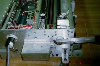
Position
Heater on the tank
|
|
 |
|
 |
|
Attach
bracket with 8-32 Screws
|
|
- Check the parts to ensure
completeness
- Unplug the machine
- Position the machine to
expose the oil tank.
- Clean the oil tank. Use
a mild solution of laundry detergent to clean the oil tank and remove
any surface contamination. Be sure to rinse the detergent off with
clean moist wipes, allow to air dry. Using a clean lint free wipe and the isopropyl
alcohol, clean the surface of the oil tank and allow to air dry.
- Noting the direction of
the wires on the heater, position the heater as shown in drawing.
(Figure 2A). Remove the adhesive
backing carefully and attach the heater to the oil tank, centering
the heater with the tank.
- Slide the protective
sleeve over the heater wires positioning it close to the heater, then
pass the wires through to the electrical compartment. Be sure to keep
the wires away from all moving belts or parts.
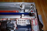
- Locate position to mount
the power module bracket. Attach loosely.
- Locate the main power
line in from socket. The L1 (Red wire).
- Run the heater power line
along the wire bundle to the power module, one wire from the heater
attaches to the male stab pin at the rear of the lighted power on/off
switch. The remaining heater
wire is attached to the short white wire, along with the length of
supplied white extension wire (Neutral).
- Route the heater wires
neatly to the power on/off module. Leaving a short service loop, trim
wires to fit if necessary. Strip the end of the first heater wire and
terminate with an insulated female crimp push terminal (supplied).
- Push the terminal firmly
onto the male tab at the rear of the power on/off rocker switch.
- Locate the Line Power
Inlet, there should be a red wire (L1), a white wire (N) and a green
wire (ground) The red fused wire from the control assembly should
be attached/spliced to the incoming L1 wire prior to the circuit breaker,
this may be accomplished by utilizing the supplied wiring connectors
or by attaching directly to the terminal block TB-1 located above
the power receptacle.
- Check all connections
to ensure to ensure proper contact.
- Attach the controller-mounting
bracket to the frame securely.
- Check to ensure that wires
are clear of all moving parts prior to securing the wires to the wiring
bundle.
- Plug in the machine.
- Power Up the unit, energize
the heater with the on/off switch.
- Confirm that the heater
is energized; the power on/off switch should be lighted, indicating
that the heater is energized. The heater temperature is self-regulating
and should provide a constant oil tank temperature.
For best results do not overfill tank. Check oil level before
each cleaning cycle.
- After all tests are complete
and the wiring is firmly attached, power off the unit.
- Close all compartments
and the machine should be ready for use.
|