 |
LANE MASTERS,
INC. 1448 Shaw Road Stockton, CA 95215-4017 |
|
http://www.LaneMasters.com
|
Telephone: 209-546-1704 |
|
[Home] [Products] [Company Information] [Technical Support] [Distributors] [Inquiry] |
 |
Installation
Instructions
Oil Heater Retrofit Kit |
The heater is designed to heat the oil in the tank to a controlled set point. Allowing the use of oil in various viscositiesto be applied regardless of ambient conditions. By heating the oil tank prior to application, the oil coating can be closely controlled regardless of room temperature. Allow the heater to warm up for a minimum of thirty minutes prior to operation, this ensures that the temperature of the oil in the tank has stabilized and consistent results can be achieved.
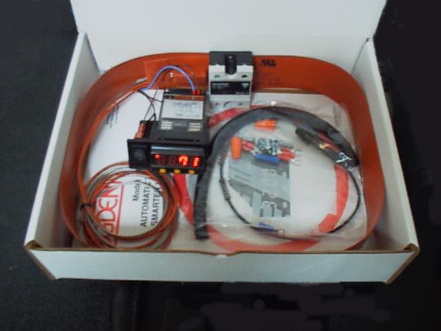
Kit consists of:
1ea.
Silicone Rubber Heater with built in thermocouple
1ea.
Temperature Controller – Ogden ETR3200
1ea.
Control Power ON/OFF Switch
1ea.
Solid State Relay
1ea.
Fuse Holder with 5 AMP fuse
1ea.
Wire attachment hardware.
1ea.
Protective Sleeve
1ea.
Controller mounting bracket with mounting screws
Required
Tools:
A
little laundry detergent
Isopropyl
Alcohol
Clean
Wipes
Small
Phillips head screwdriver
Small
adjustable end wrench
Wire Cutters
Wire
Stripper
Crimp tool
Installation Instructions:
- Check the parts to ensure completeness
- Unplug the machine.
- Place the machine in an upright position to expose the oil tank.
- Clean the oil tank in the area where the heater is to be attached. Use a mild solution of laundry detergent to clean the oil tank and remove any surface contamination. Be sure to rinse the detergent off with clean moist wipes, allow to air dry. Using a clean lint free wipe and the isopropyl alcohol, clean the surface of the oil tank and allow to air dry.
- Note the direction of the wires on the heater (the heater can be positioned on either end of the tank). Remove the adhesive backing carefully and attach the heater to the oil tank, centering the heater with the tank. (Figure 2A) ). Heater should be mounted on a clean flat surface avoiding welds and edges. It is important that full contact is made between the heater and tank surface (uneven contact will cause hot spots on the heater, and result in premature heater failure).
- Slide the protective sleeve over the heater wires positioning it close to the heater, then pass the wires through to the electrical compartment. Be sure to keep the wires away from all moving belts or parts.
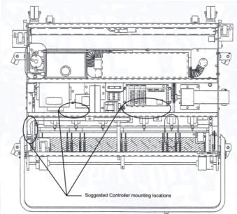
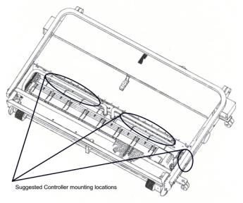
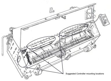
- Locate position to mount the control assembly bracket. Position loosely because the supply voltage, heater and thermocouple wires need to be attached. Utilize the spacing on the solenoid wick wall or drill and tap (8-32) holes on the sidewall of the machine for this attachment. The assembly consists of the controller mounting bracket and the separately mounted solid-state relay. Refer to the attached drawing for suggested mounting locations, locate equipment away from motors and other devices that may cause excessive noise. Wiring should be neatly bundled and located away from any moving parts.
- Locate the main power socket line in. The L1 (Brown, Red or Black wire depending on machine color code scheme).
- The smaller pair of wires are the J thermocouple wires (Red -/White +) with stainless steel metal overbraid.
- Run the heater power line and sensor wires along the wire bundle and attach the sensor wires to the rear of temperature controller. Attach the red sensor wire (-) to terminal # 10 and the white sensor wire (+) to terminal # 11 on the rear of temperature controller.
- Attach one heater power wire to terminal marked "T1" on the solid state relay, the other heater power wire should be attached to the white (neutral) supply. *The blue (neutral) wire from the temperature control assembly is also be connected to the neutral supply.
- Locate the Line Power Inlet; there should be a red wire (L1), a white wire (N) and a green wire (ground). connect one end of the "fused" wire (supplied) to the incoming L1 wire prior to the circuit breaker; this may be accomplished by utilizing the supplied wiring connectors or by attaching directly to the terminal block TB-1 located above the power receptacle. In event the machine has dual inlets, attach the power line after SW1 and before the circuit breaker CB-1. Attach the other end of the fused wire, and the brown wire from the controller on/off switch to the solid state relay terminal marked "L1".
- Connect the blue wire from the temperature controller and the remaining heater wire to supply Neutral.
- Connect the purple wire (from terminal 6 of the controller) to terminal marked A1(+), and the grey wire (from terminal 5 of the controller) to the terminal marked A2(-) on the solid state relay.
- Check all connections to ensure proper contact.
- Affix the controller mounting bracket to the frame securely.
- Check to ensure that wires are clear of all moving parts prior to securing the wires to the wiring bundle.
- Plug in the machine.
- Power Up the unit, the controller should energize, if not, check the on/off switch by the temperature controller. The controller should energize and display the temperature of the heater.
- Set the controller to the desired temperature, confirm all settings on controller (refer to temperature controller manual).
- Confirm that the heater is energized; there should be a steady red light on the upper left corner of the controller, indicating that the controller is energizing the solid state relay. As the temperature of the heater approaches set point, the indicator should blink, indicating that the controller is pulsing power to the heater.
- After all tests are complete and the wiring is firmly attached, power off the unit.
- Close all compartments and the machine should be ready for use.
 |
 |
|
Heater
Mounting Location (Phoenix)
|
Heater
Mounting Location LaneWalker
|